Running ScaleIO in the HomeDC

In this Post, I will describe how I have come about in deploying a ScaleIO Software-Defined Storage in the Home Datacenter. Over the course of 2016, I have upgraded my clusters from VMware Virtual SAN Hybrid (Flash for Caching Tier and SAS Enterprise disks for Capacity Tier) to an All Flash Tiering. This has released Multiple 4TB SAS Enteprise disk from the vSAN config. Rather than remove these from the hosts, I decided to learn and test the Free and Frictionless edition of DellEMC ScaleIO.

My ScaleIO design crosses the boundaries of three VMware vSphere Clusters, and is hosted across eight Tower case servers in the Home Datacenter. In a normal production ScaleIO cluster, the recommendation is to have a minimum of 6 disk drivers per  ScaleIO Data Server (the servers shading the storage). As you will see, in my design I spread the SAS Enterprise disks across the eight servers.

I’m not going to cover the definition of Protection Domains or Storage Pools in this article, but for this design, I have a single Protection Domain (pd1) with a single Storage Pool which I named SAS_pool. I did device the Protection Domain into three separate Fault Sets (fs1, fs2 and fs3), so as to spread failures across the hosts based on the power phase use in my datacenter.

I’ve run ScaleIO across my cluster for 10 months for some specific workloads that I just could not fit or did  not want to fit on my VMware vSAN All-Flash environment.

Here is a large screenshot of my ScaleIO configuration as it’s re-balancing the workload across the hosts. 


Each ScaleIO Data Server (SDS) was a CentOS 7 VM running on the ESXi and had two or three physical devices attached to it using RDM. Each SDS had a SSD device for the RFcache (Read Cache) and a single or dual SAS disk drive.

At the peak this deployment, the ScaleIO config had 41.8TB Usable Storage. I set the Spare Capacity at 8TB, leaving 34.5TB usable storage. With the double parity on the storage objects, I could only store 17.2TB of data to my VMs and my vSphere hosts.

Over the past 10 month of using ScaleIO, I’ve found two main limitations.

  1. The ScaleIO release cycle, and even more so for people using the Free & Frictionless version of ScaleIO. The release cycle is out of sync with the vSphere release. Some version are only released to Dell EMC customer with support contracts, and some version take between 6 and 8 weeks to move from the restricted access to a public access. At the end of March 2017, there was no version of ScaleIO that supports vSphere 6.5.
  2. Maintenance & Operations. As I wanted or needed to upgrade an ESXi host with a patch, a driver change or install a new version of NSX-v, I had to plan the power off the SDS VM running on the ESXi host. You can only put a single SDS in a planned maintenance mode per Protection Domain. So only one ESXi could be patched at a time. A simple cluster upgrade process with a DRS backed network, would now take much longer require more manual steps, put the SDS VM in maintenance mode, shutdown the SDS VM (and take the time to patch the Linux in the SDS VM), putting the host in maintenance mode, patching ESXi, restarting ESXi, exit maintenance mode, restart the SDS VM, exit the ScaleIO Maintenance mode, wait for the ScaleIO to rebuild the redundancy and move to the next host.

I’ve now decommissioned the ScaleIO storage tier as I needed to migrate to vSphere 6.5 for some new product testing.

Network core switch Cisco Nexus 3064PQ

Here is my new network core switch for the Home Datacenter, a Cisco Nexus 3064PQ-10GE.

Cisco Nexus 3064PQ-10GE (48x SFP+ & 4x QSFP+)

Cisco Nexus 3064PQ-10GE (48x SFP+ & 4x QSFP+)

But before I speak more about the Cisco Nexus 3064PQ-10GE, let me just bring you back in time… Two years ago, I purchased a Cisco SG500XG-8F8T 16-port 10-Gigabit Stackable Managed Switch. This was first described in my Homelab 2014 build. This was my most expensive networking investment I ever did. During the past two years, as the lab grew, I used the SG500XG and two SG500X-24 for my networking stack. This stack is still running on the 1.4.0.88 firmware.

sg500xg_stack

During these past two years, I have learned the hard way that network chipsets for 10GbE using RJ-45 cabling was outputting so much more heat than the SFP+ chipset. My initial Virtual SAN Hybrid implementation using a cluster of three ESXi host with Supermicro X9SRH-7TF (Network chipset is Intel X540-AT2) crashed more than once, when the network chipset became so hot that I lost my 10G connectivity, but the ESXi host kept on running. Only a powerdown & cool off of the motherboard, would allow my host to restart with the 10G connectivity. This also lead me to expand the VSAN Hybrid cluster from three to four hosts and to have a closer look at the heating issues when running 10G over RJ45.

Small business network switches with 10GBase-T connectivity are more expensive than the more enterprise oriented SFP+ switch, but they also output so much more heat (Measured in BTU/hr). Sure once the 10GBase-T switch is purchased, the cost of Category 6A cables is cheaper than getting the Passive Copper cables, who are limited to 7 meters.

The Cisco SG500XG-8F8T is a great switch as it allows me to connect using both RJ-45 and SFP+ cables.

As the lab expanded, I started to ensure that my new hosts have either no 10GBase-T adapters on the motherboard, or use the SFP+ adapter (Like my recent X10SDV-4C-7TP4F ESXi host). I have started using the Intel X710 Dual SFP+ adapters on some of my host. I like this Intel network adapter, as the network chipset gives out less heat than previous generations chipset, and has a firmware update function that can done from the command prompt inside of vSphere 6.0.

This brings me to the fact that I was starting to run out of SFP+ ports as the labs expands. I have found on ebay some older Cisco Nexus switch, and the one that caught my eye for it’s amount of ports, it price and it’s capabilities is the Cisco Nexus 3064PQ-10GE. These babies are going for about $1200-$1500 on ebay now.

3064pq_on_ebay

The switch comes with 48-ports SFP+ and 4-ports in QSFP+ format. These four ports can be configured in either 16x10G using fan-out cables or 4x40G. This is a software command that can be put on the switch to change from one mode to the other.

Here is my switch with the interface output. I’m using a Get-Console Airconsole to extend the console port to my iPad over Bluetooth.

nexus_3064pq_10g_40g-1

My vSphere 6.0 host is now connected to the switch using an Intel XL710-QDA2 40GbE network adapter and a QSFP+ copper cable.

esxi_40G

I’m going to use the four QSFP+ connectors on the Cisco Nexus 3064PQ-10GE to connect my Compute cluster with NSX and VSAN All-Flash.

3064_10g_40g_show_int


The switch came with NX-OS 5.0(3)U5(1f).

3068_nx-os


Concerning the heat output of the Cisco Nexus 3064PQ-10GE (datasheet) I was pleasantly surprised to note that it’s output is rather small at 488 BTU/hr when all 48 SFP+ are used. I also noted that the noise level of the fans was linked to the fan speed and the charge of the switch. Going from 59 dBA at 40% duty cycle to 66 dBA at 60% duty cycle to 71 dBA when at 100% duty cycle.

Here is the back of the Cisco Nexus 3064PQ-10GE. I did purchase the switch with a DC power (top of switch to the right), because the switch I wanted had both the LAN_BASE_SERVICES and the LAN_ENTERPRISE_SERVICES license. I sourced two N2200-PAC-400W-B power supply from another place.

nexus_3064pq_back-1

Link to the Cisco Nexus 3064PQ Architecture.


Intel Xeon D-1518 (X10SDV-4C-7TP4F) ESXi & Storage server build notes

These are my build notes of my last server. This server is based around the Supermicro X10SDV-4C-7TP4F motherboard that I already described in my previous article (Bill-of-Materials). For the Case I select a Fractal Design Node 804 square small chassis. It is described as being able to handle upto 10x 3.5″ disks.

Fractal Design Node 804

Here is the side view where the motherboard can be fitted. It supports MiniITX, MicroITX and the FlexATX of the Supermicro motherboard. Two 3.5″ harddrives or 2.5″ SSD can be fitted on the bottom plate.

x10sdv_node804--2

The right section of the chassis, contains the space for eight 3.5″ harddrives, fixed in two sliding frame at the top.

x10sdv_node804--3

Let’s compare the size of the Chassis, the Power Supply Unit and the Motherboard in the next photo.

Fractal Design Node 804, Supermicro X10SDV-4C-7TP4F and Corsair RM750i

Fractal Design Node 804, Supermicro X10SDV-4C-7TP4F and Corsair RM750i

When you zoom in the the picture above, you can see three red squares on the bottom right of the motherboard. Before you inser the motherboard in the chassis, you might want to make sure you have moved the mSATA pin from the position on the photo to the 2nd position, otherwise you will not be able to attach the mSATA to the chassis. You need to unscrew the holding grommet from below the motherboard. People having purchased the Supermicro E300-8D will have a nasty surprise. The red square in the center of the motherboard is set for M.2 sticks at the 2280 position. If you have a M.2 storage stick 22110, you better move the holding grommet also.

Here is another closer view of the Supermicro X10SDV-4C-7TP4F motherboard with the two Intel X552 SFP+ connectors, and the 16 SAS2 ports managed by the onboard LSI 2116 SAS Chipset.

X10SDV-4C-7TP4F

In the next picture you see the mSATA holding grommet moved to accommodate the Samsung 850 EVO Basic 1TB mSATA SSD, and the Samsung SM951 512GB NVMe SSD in the M.2 socket.

X10SDV-4C-7TP4F

In the next picture we see the size of the motherboard in the Chassis.At the top left, you will see a feature of the Fractal Design Node 804. A switch that allows you to change the voltage of three fans. This switch is getting it’s electricity thru a SATA power connector. It’s on this power switch, that I was able to put a Y-power cable and then drive the Noctua A6x25 PWM CPU fan that fits perfectly on top of the CPU heatsink. This allowed me to bring down the CPU heat buildup during the Memtest86+ test from 104c to 54c.

X10SDV in Node 804

I used two spare Noctua Fan on CPU Heatsink fixer to hold the Noctua A6x25 PWM on the Heatsink, and a ziplock to hold those two fixers together (sorry I’m not sure if we have a proper name for those metal fixing brackets). Because the Noctua is getting it’s electricity from the Chassis and not the Motherboard, the Supermicro BIOS is not attemping to increase/decrease the Fan’s rpm. This allows me to keep a steady air flow on the heatsink.

Noctua A6x25 PWM fixed on heatsink

Noctua A6x25 PWM fixed on heatsink

I have fitted my server with a single 4TB SAS drive. To do this I use a LSI SAS Cable L5-00222-00 shown here.

lsi_sas_l5-00222-00_cable

This picture shows the 4TB SAS drive in the left most storage frame. Due to the length of the adapter, the SAS cable would be blocked by the Power Supply Unit. I will only be able to expand to 4x 3.5″ SAS disk in this chassis. Using SATA drives, the chassis would take upto 10 disks.

Node 804 Storage and PSU side

View from the back once all is assembled and powered up.

x10sdv_node804--12

This server with an Intel Xeon D-1518 and 128GB is part of my Secondary Site chassis.

ESXi60P03

The last picture shows my HomeDC Secondary Site. The Fractal Design Node 804 is sitting next to a Fractal Design Define R5. The power consumption is rated at 68 Watts for a X10SDV-4C-7TP4F with two 10GbE SFP+ Passive Copper connection, two SSDs and a single 4TB SAS drive.

HomeDC Secondary Site

HomeDC Secondary Site

Supermicro X10SDV-4C-7TP4F server Bill-of-Materials

Another new host has joined the Home Datacenter (#HomeDC). This one is my first low powered Intel Xeon D-1500 server I get my hands on. There have been some great install guides about other Supermicro X10SDV motherboards on many sites, and I would recommend that you head over to Paul Braren’s (@tinkertry) TinkerTry site for a lot of great content. There are now also two small server from Supermicro that came out E200-8D and E300-8D. The motherboard I selected for my new host closely matches the one on the Supermicro E300-8D, described on TinkerTry.

I was looking for a motherboard that had great storage capabilities, 10G connectivity and low powered. As my Home Datacenter (#HomeDC) is growing, I find myself using more and more 10G SFP+ connectivity. This 10G SFP+ connectivity consumes less watts in the chipset, creating less heat inside the servers. SFP+ connecitivty allows me to use cheaper network switches. 10G Ethernet with RJ45 has a price premium, even if the Category 6A cables are cheaper than Passive Copper SFP+ cables.

I selected the Supermicro X10SDV-4C-7TP4F motherboard, it has a 7 year product life, support two SFP+ 10G connection, comes with a LSI/AVAGO 2116 SAS/SATA chipset with a total of 16 SAS ports. More than enough for a storage server. It comes with a M.2 socket and a mSATA socket. The Intel Xeon D-1518 is a quad cores processor running at 2.2Ghz. All in all a very good selection of specifications on such a small FlexATX motherboard.

X10SDV-7TP4F_spec

The X10SDV series of motherboards come with the Intel X552 dual 10G network card. In case you are experiencing network connectivity issues, it is important to make sure your motherboard has the proper firmware. When I received my motherboard with the default bios 1.0, it gave me a serious scare. I was unable to get the two 10G links up with my Cisco SG500X and SG500XG switches. I had to upgrade to version 1.0a and clear the CMOS to get it to work.

I’ve been a long time user of the Fractal Design cases, and I wanted to have something small for the FlexATX, yet with lots of space for adding disks. So I selected the Fractal Design Node 804 cube chassis that supports MicroATX, MiniATX and the FlexATX like the Supermicro X10SDV series. The Node 804 is capable of having upto 10x 3.5″ disks. The case comes with three fans and a fan selector that is powered by a SATA power connector, so fans can run independant of the motherboard connectors. This is very usefull when you add a small Noctua NF-A6x25 PWM fan on top of the CPU heat sink. It is not spinning-up and down at the whim of the Supermicro motherboard choosing. I also liked the square look of the chassis.

fd-ca-node-804

For my power supply, I have decided to change from my usual Enermax for a Corsair RM750i power supply. I wanted a power supply that was capable of driving a lot of disks if I decided to increase the amount of disks, and a power supply that would be quiet under low power consumption. As you see below plenty of expansions and a power supply that stays fan-less until it it’s 45% of it’s charge. I added a Seagate Enterprise Capacity 4TB SAS drive in the chassis and when it’s running vSphere with some quiet VMs, the system is only consuming 69 Watts.

RMi_750_04RM750i_NOISE_WEB_121714

The Supermicro X10SDV-4C-7TP4F comes with the following expansions for storage.

PCI-Express
  • 2 PCI-E 3.0 x8 slots
M.2
  • Interface: PCI-E 3.0 x4
  • Form Factor: M Key 2242/2280/22110
  • Support SATA devices
Mini PCI-E
  • Interface: PCI-E 2.0 x1
  • Support mSATA

In the M.2 socket, I added a Samsung SM951 512GB NVMe Solid State Disk and in the Mini PCI-E, I added the Samsung 850 EVO 1TB Basic Solid State Disk. The mSATA drive is used as the Boot device and to have a large datastore to keep VMs local to the host. The Samsung SM951 512GB NVMe SSD can be used for the caching part of a VSAN design or a rfcache when running scaleIO.

Another up front warning, before you place this motherboard in a chassis, you need to make sure to un-screw the mSATA holder stick to the right position, so you can use a standard mSATA. There is a tiny screw on top and bottom of the mSATA holding bolt.

The Supermicro X10SDV-4C-7TP4F CPU cooling is done with a passive CPU heat sink. But during the initial memory testing, I have found that the IPMI CPU Sensor was showing Critical heat warning during a memtest86+ run. I decided to add the Noctua A6X25 PWM fan on top of Xeon D-1518 processor. The fit is perfect, and when this fan is connected on the chassis fan subsystem (see the top right section in the photo at the bottom) the critical heat issues disappeared.

So let’s recap the Bill-of-Materials (BoM) for this server the way I have configured. The pricing has been assembled from amazon/newegg in the US, amazon/azerty.nl for the Euro and with Brack.ch for Switzerland. I have left out the cost of the HDD, as Your Mileage May Vary.

X10SDV Cost

I will create a 2nd post on the build notes and pictures, but here is a teaser.

Node804_X10SDV


Intel NUC Skull Canyon (NUC6I7KYK) and ESXi 6.0

As part of my ongoing expansion of the HomeDC, I was excited to learn about the availability of the latest Quad-Core Intel NUC a few months ago. Last friday I received my first Intel NUC Skylake NUC6I7KYK. I only started setting it up this afternoon. I usually do disabled a few settings in the BIOS, but following the warning from fellow bloggers that people had issues getting the Intel NUC running with ESXi [virtuallyghetto.com] I did take a deeper look prior to the install. I was able to install ESXi 6.0 Update 2 (Build 3620759) on my 4th try after disabling more settings in the BIOS.

Here is the screenshot of the ESXi Host Client of the Intel NUC6I7KYK with BIOS 0034.

nuc6i7kyk_ehc

Here is a quick screenshot of the physical machine. I was planning to use the SDXC slot with an SDXC 32GB card to store the boot configuration of ESXi, but unfortunately I did not see the SDXC as a valid target during the ESXi install process. So I keep the USB key I was boot from and select it as the target. On the screenshot below you will also notice an extra Network card, the StarTech USB3 Gigabit Ethernet Network Adapter which driver you can get from VirtuallyGhetto’s web page Functional USB 3.0 Ethernet Adapter (NIC) driver for ESXi 5.5 & 6.0. Thanks William for this driver.

nuc6i7kyk_startech

The Bill-of-Materials (BOM) of my assembly…

Here below you can see the Intel NUC with the two Samsung SM951 NVMe disks and the Crucial memory.nuc6i7kyk_open

To get ESXi 6.0 Update 2 to install I disabled the following BIOS Settings.But as people have commented back after more test, you really only need to disable the Thunderbolt Controller to get ESXi to install.

BIOS\Devices\USB

  • disabled – USB Legacy (Default: On)
  • disabled – Portable Device Charging Mode (Default: Charging Only)
  • not change – USB Ports (Port 01-08 enabled)

BIOS\Devices\SATA

  • disabled – Chipset SATA (Default AHCI & SMART Enabled)
  • M.2 Slot 1 NVMe SSD: Samsung MZVPV256HDGL-00000
  • M.2 Slot 2 NVMe SSD: Samsung MZVPV512HDGL-00000
  • disabled – HDD Activity LED (Default: On)
  • disabled – M.2 PCIe SSD LEG (Default: On)

BIOS\Devices\Video

  • IGD Minimum Memory – 64MB (Default)
  • IGD Aperture Size – 256MB (Default)
  • IGD Primary Video Port – Auto (Default)

BIOS\Devices\Onboard Devices

  • disabled – Audio (Default: On)
  • LAN (Default)
  • disabled – Thunderbolt Controller (Default: On)
  • disabled – WLAN (Default: On)
  • disabled – Bluetooth (Default: On)
  • Near Field Communication – Disabled (Default is Disabled)

BIOS\Devices\Onboard Devices\Legacy Device Configuration

  • disabled – Enhanced Consumer IR (Default: On)
  • disabled – High Precision Event Timers (Default: On)
  • disabled – Num Lock (Default: On)

BIOS\PCI

  • M.2 Slot 1 – Enabled
  • M.2 Slot 2 – Enabled
  • M.2 Slot 1 NVMe SSD: Samsung MZVPV256HDGL-00000
  • M.2 Slot 2 NVMe SSD: Samsung MZVPV512HDGL-00000

Cooling

  • CPU Fan Header
  • Fan Control Mode : Cool

Performance\Processor

  • disabled Real-Time Performance Tuning (Default: On)

Power

  • Select Max Performance Enabled (Default: Balanced Enabled)

Secondary Power Settings

  • disabled – Intel Ready Mode Technology (Default: On)
  • disabled – Power Sense (Default: On)
  • After Power Failure: Power On (Default was stay off)

Sample view of the BIOS Onboard Devices as I deactivate some Legacy Device Configuration.

nuc6i7kyk_bios_onboard


26/05 Update: Only the Thunderbolt Controller is stopping the ESXi 6.0 Update 2 installer to run properly. Re-activiting it after the install does not cause an issue in my limited testing.

Using virtual synology in a scale out distributed storage architecture

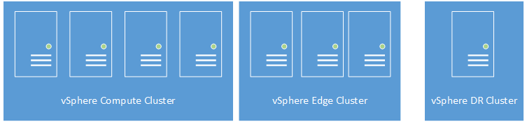
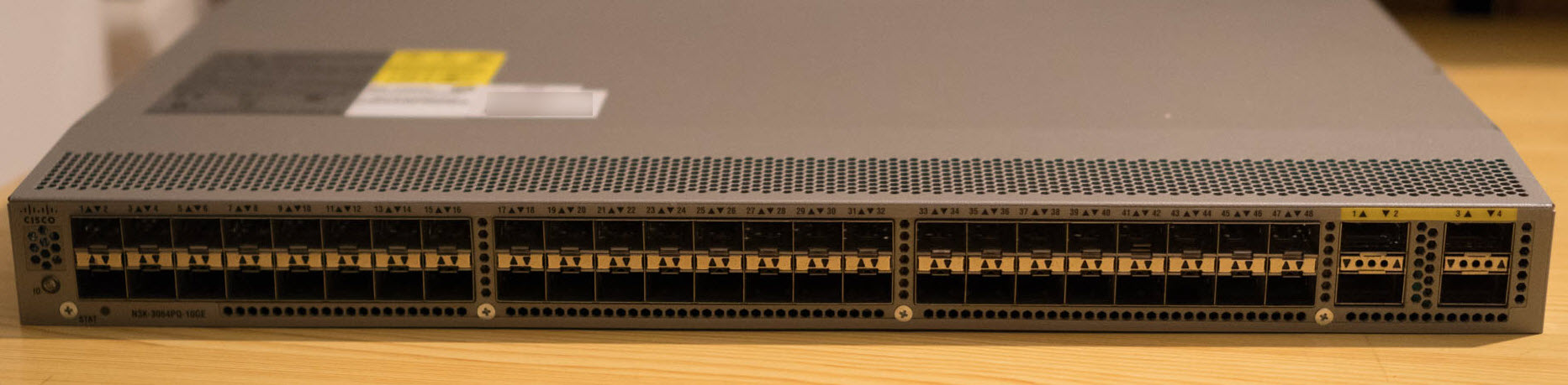
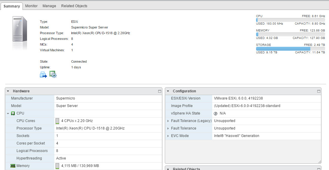
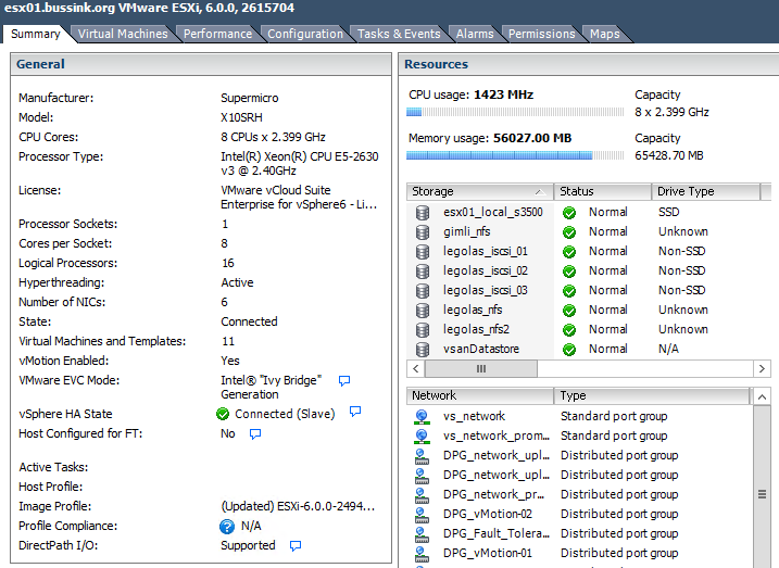
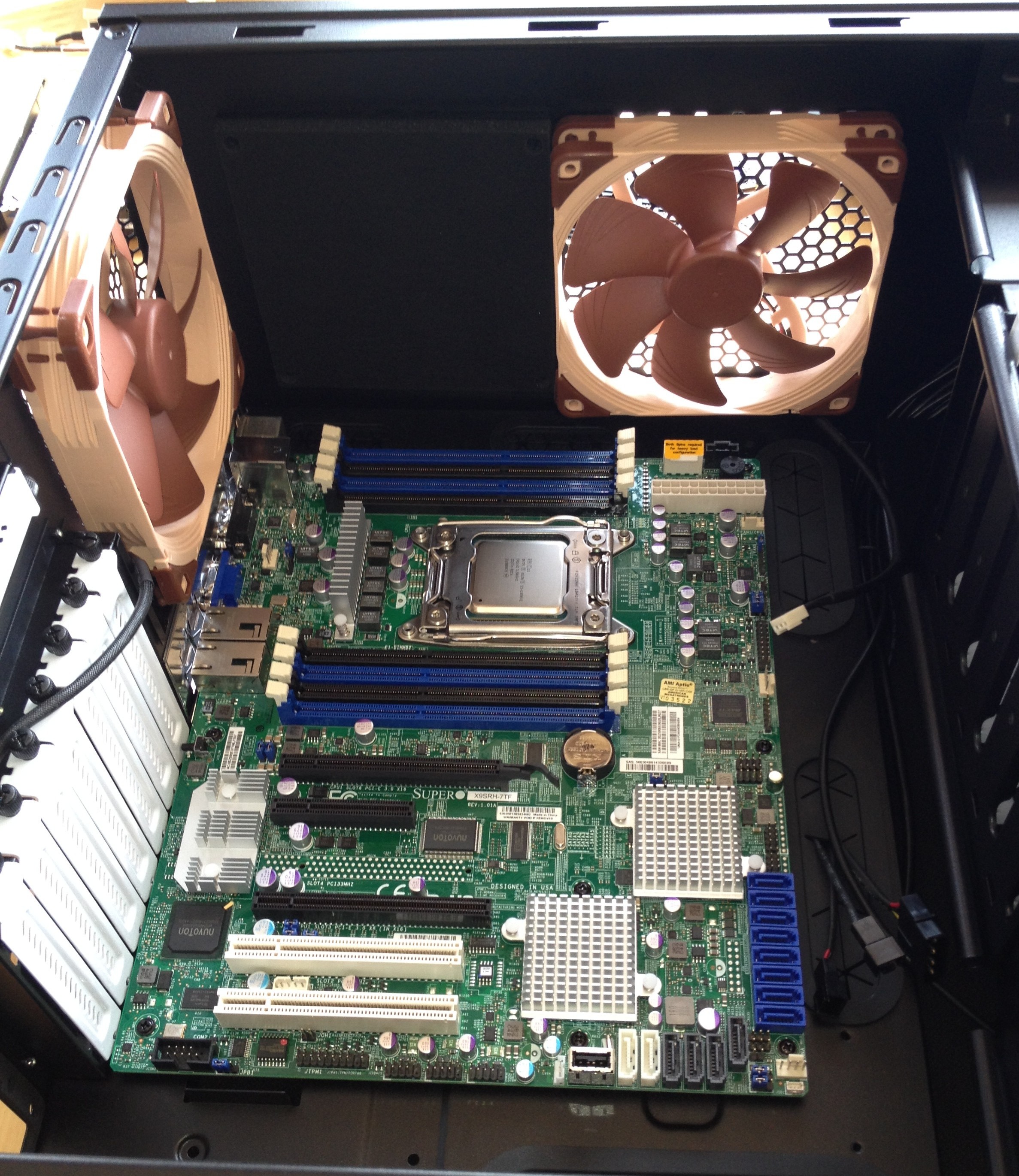
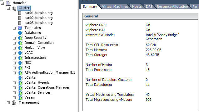
I’ve recently finished upgrading the Home Datacenter (#HomeDC) to vSphere 6.0 with four hosts running VSAN 6.0 with dual 10GbE networking for each host.

vsan

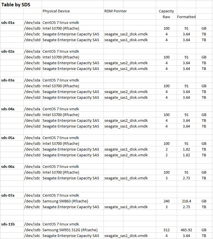
Even running a few large virtual machines on the VSAN Datastore like VDP 6.0 with a 4TB backed disk, I found myself with a lot of spare storage. I’ve invested in the SAS disks (Seagate Enterprise Capacity 4TB SAS 7200rpm) backing the VSAN datastore, so the budget is gone for replacing the aging Synology DS1010+.

I’ve recently studied various reviews on the Synology DS2015xs, but found the CPU a bit lacking to drive the dual 10GbE SFP+ links, and the Synology DS3615xs is a bit expensive. So why not leverage the 10GbE NICs in my management cluster for ultra fast connections, the fast CPUs on my hosts are a nice addition too. The biggest advantage is “cheap” 10GbE file server connections.

The rest of the blog is going in a grey zone… it’s #unsupported

Let me show you the goods first.

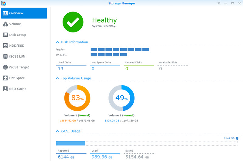
virtual Synology DS3615xs running on VSAN datastore

The concept is to create a storage appliance, that leverages the VSAN datastore and its accelerations of read/writes, and provides a flexible structure, where you could increase the storage on an as needed basis, or create a temporary storage while migrating from one Synology to a newer one. All this running on a vSphere host. A concept that a lot of other companies are doing with their Virtual Storage Appliances.

I’m going to use the XPEnology operating system, which is based on the Synology DiskStation Manager (DSM).

  • In my design and implementation that I will describe here, the virtual synology has a 8TB disk. The appliance is not doing any RAID functions on this disk, as its already protected on the VSAN datastore using a number of failures to tolerate of 1 policy (FTT=1).
  • Another way would be to create two or four virtual disks with a number of failures to tolerate of 0, and do a Software RAID in the appliance.
  • A third way could be to use four physical disks and two SSDs on a host, create RDM links, and present all these disks to the virtual Synology appliance and do Software RAID on the disks, and use the SSD for caching (SSDcache). This virtual storage appliance would not be able to move to another host using vMotion, but you could mitigate this restriction using Synology High-Availability.

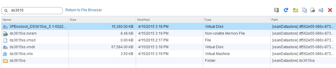
To build the virtual synology you will need to retrieve the latest copy of the XPEnology DS3615xs files. You are looking for XPEnoboot_DS3615xs_5.1-5022.3.vmdk or a more recent version. Each version can have its own deployment process. The process I have described below is using the XPEnoboot_DS3615xs_5.1-5022.3.vmdk version.

There is also a huge forum with lots of contributions and interesting links at the XPEnology forums.

1) Creating the vSynology

Now I’m going to say upfront, that you will need to upload the XPEnoboot_DS3615xs_5.1-5022.3.vmdk twice in the virtual storage appliance. Once for the initial install, which will format all disks of the appliance (including the boot vmdk), then again to boot the appliance.

We start by creating a new Virtual Machine.

01 - Create new VM

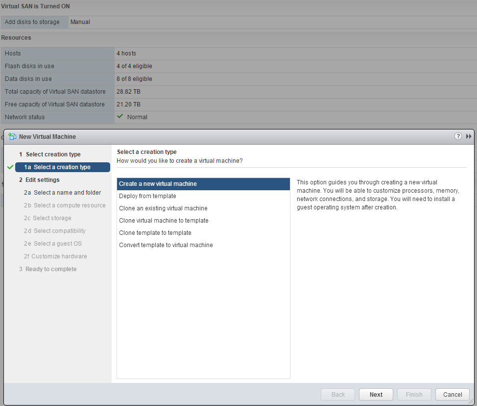
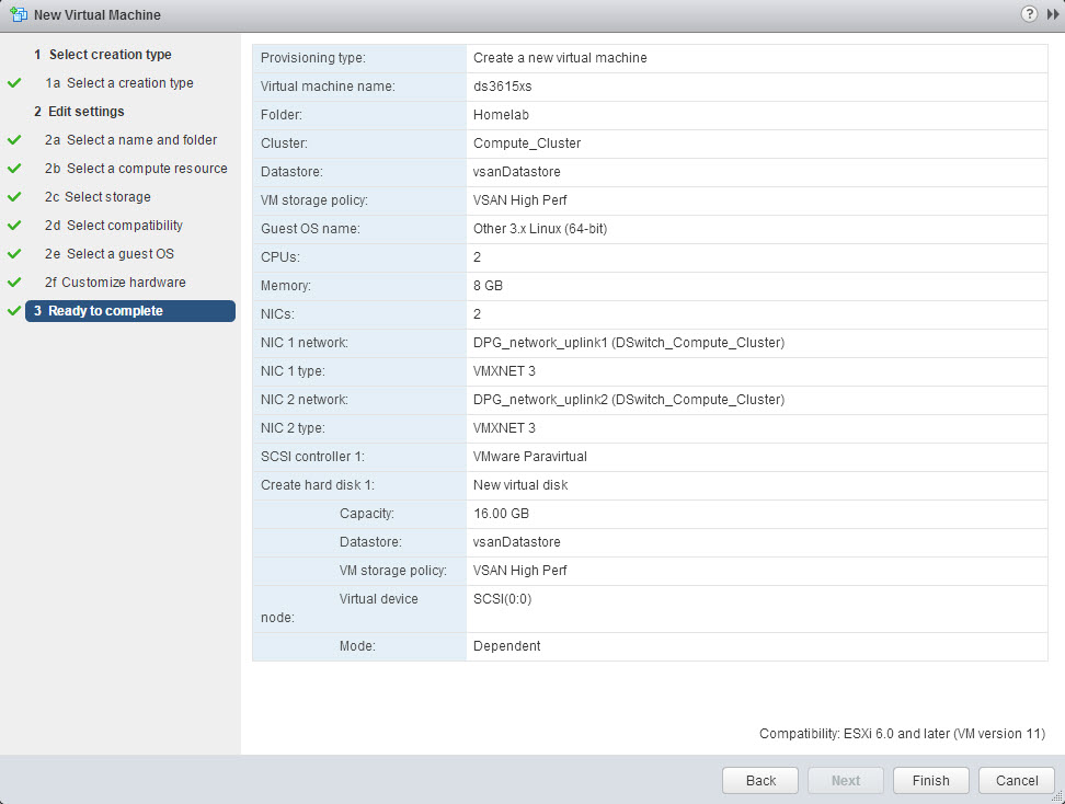
We give it a name and place it in a Cluster.

02 - Name VM

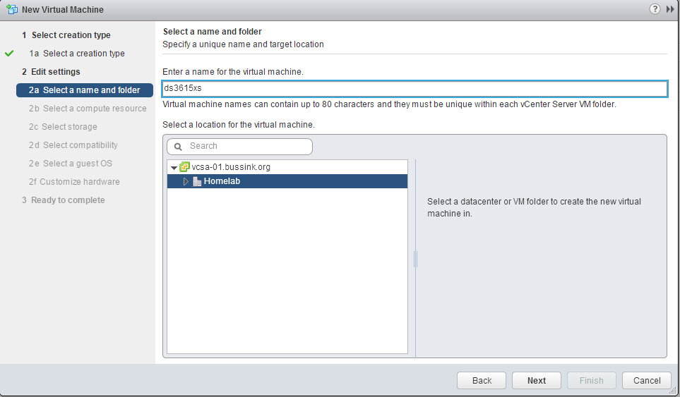
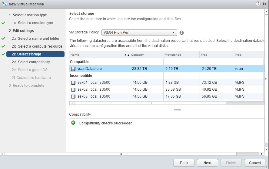
And we store the virtual machine and its configuration files on an existing datastore. I have select my vsanDatastore.

04 - Select VSAN Datastore

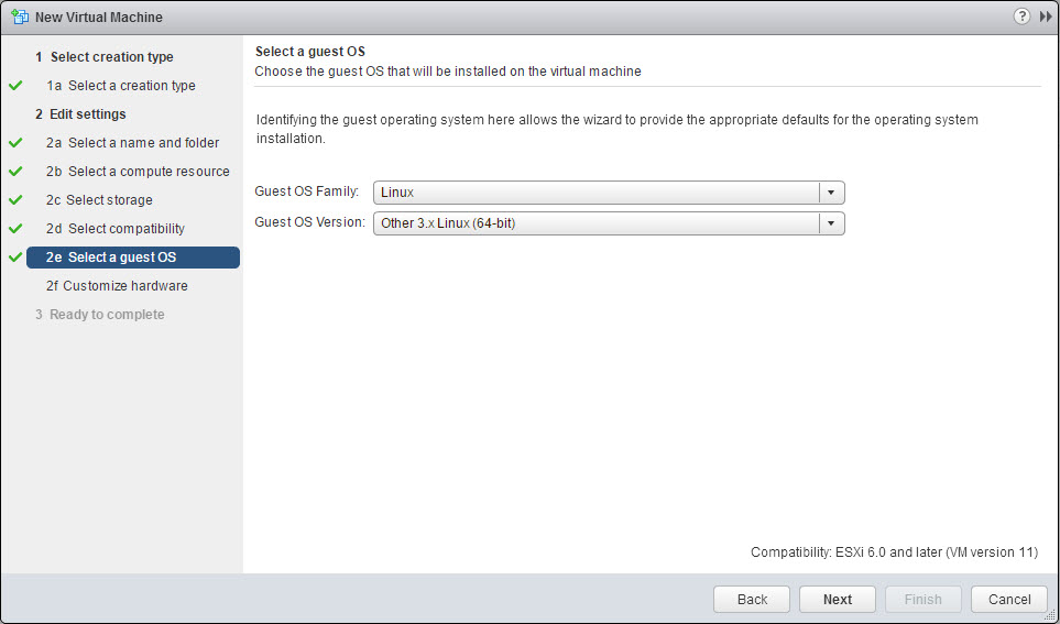
We define the hardware compatibility of the virtual machine and select the Guess OS. We are going to use the Linux Other 3.x Linux (64-bit).

06 - Select Guess OS Linux 3.2I have selected two CPU and 8GB of memory. Because my appliance won’t do any software RAID, 2 vCPU is more than enough.

07 - Base Hardware

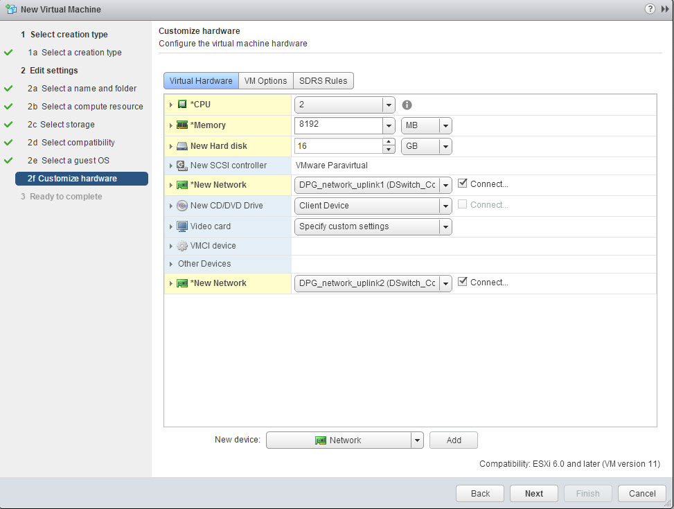
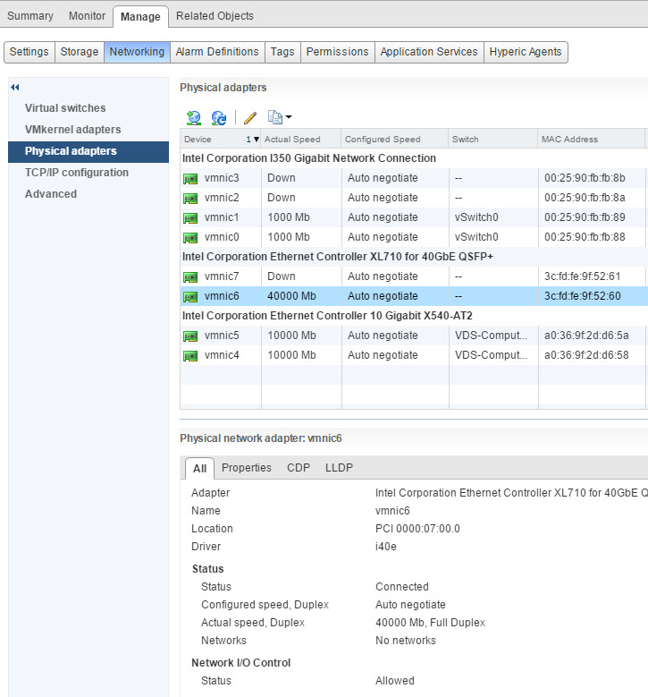
I have added a second VMXNET3 network interface, which I put on a dedicated 10GbE Distributed Port Group. So eth0 goes out using uplink1 and eth1 goes out using uplink2. You see these changes in the summary of the appliance below.

08 - ds3615xs Hardware Summary2) Changing the Boot disk

We can now go back into the appliance and edit it. We remove the boot disk, and erase it from the disk. (Yeah missing screenshot of this step).

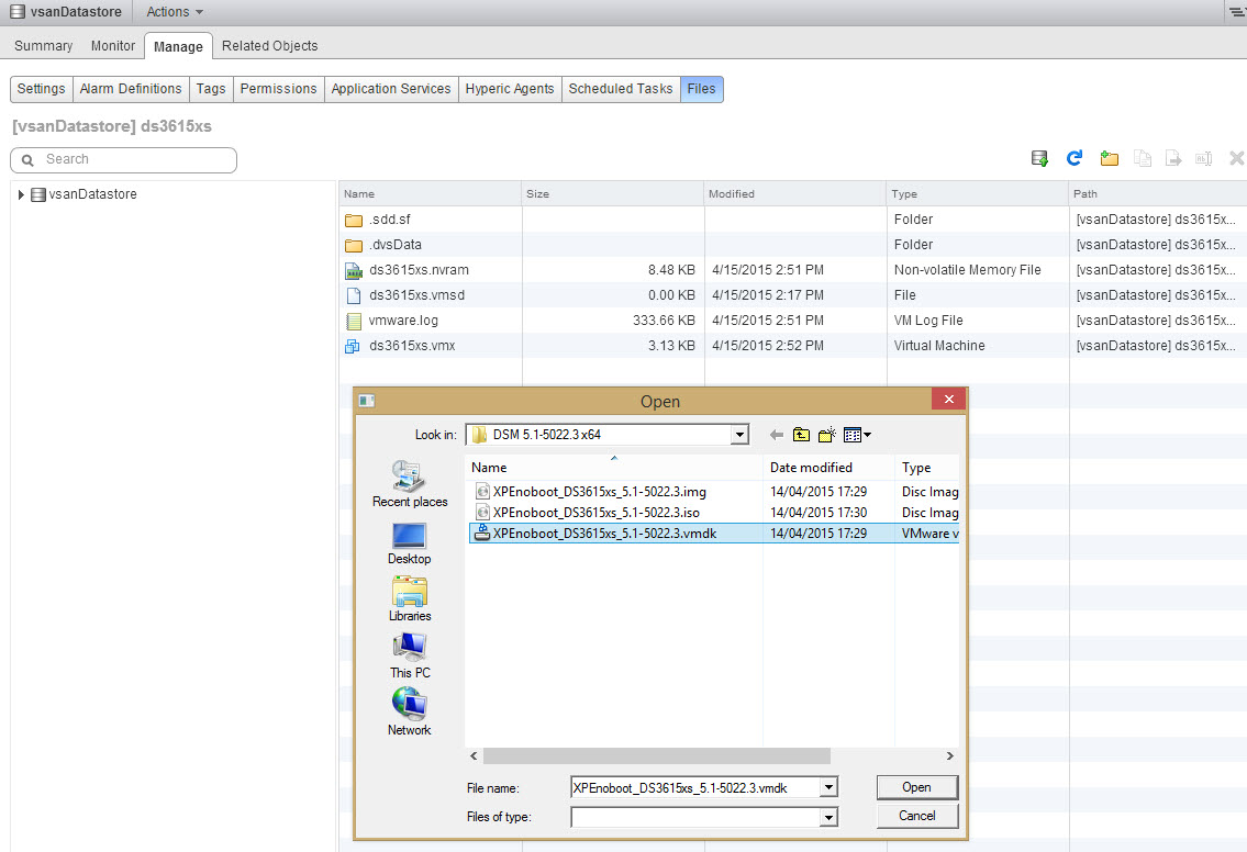
We then use the datastore browser to upload for the first time the XPEnoboot_DS3615xs_5-1-5022.3.vmdk in the appliance folder.

09 - Upload XPE vmdk on vsanDatastore

And we add this existing virtual disk to the appliance

10a - Select the XPE vmdk

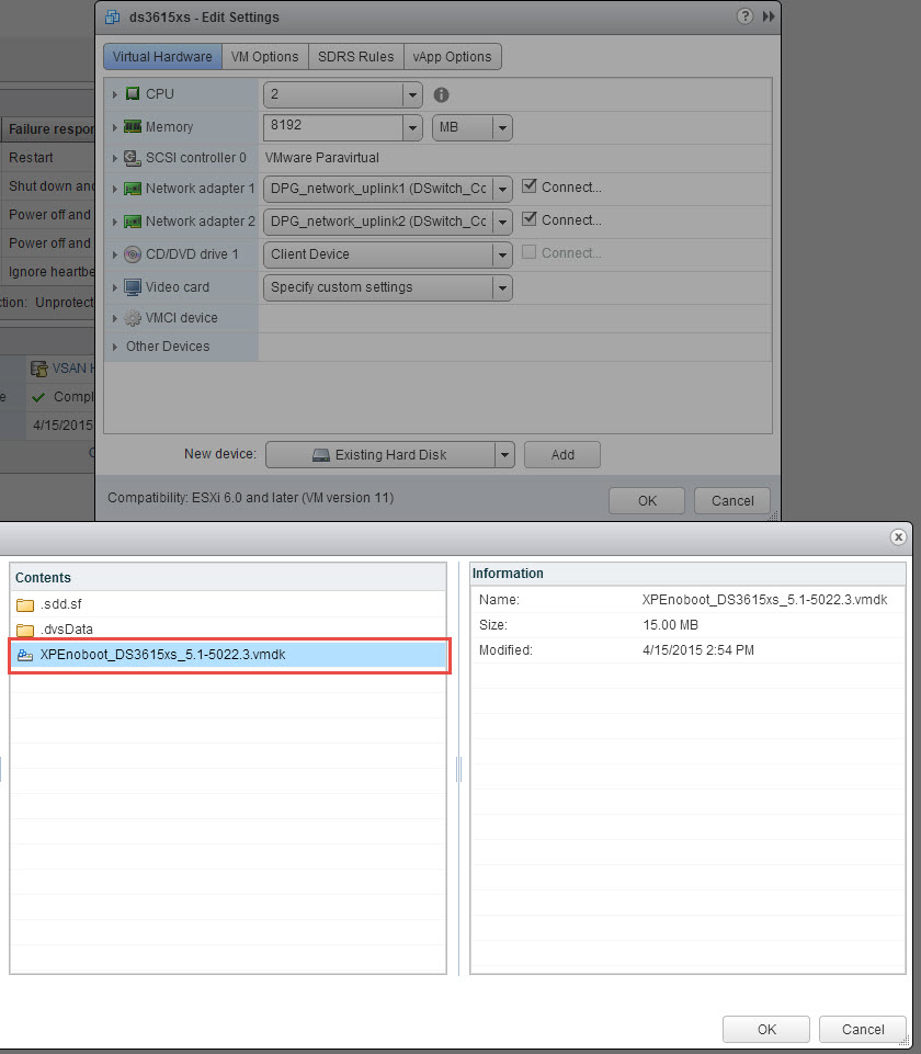
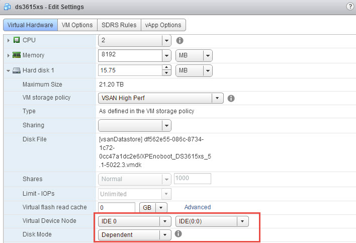
The new boot disk is attached as an IDE disk on port IDE(0:0)

10b - Add XPE vmdk as IDE0-0

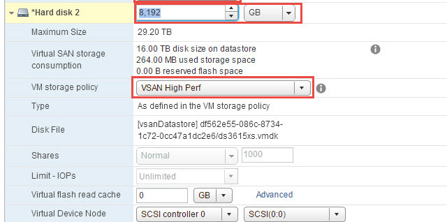
In the following screenshot, I’m adding the main disk to the storage appliance. I’m creating a 8TB (or 8192GB) virtual disk, and select my VSAN Storage Base Polci “VSAN High Perf”.  The “VSAN High Perf” is defined as a Number of failures to tolerate of 1, and Number of disk stripes per object at 2.

11 - XPE non-persistent and 8TB

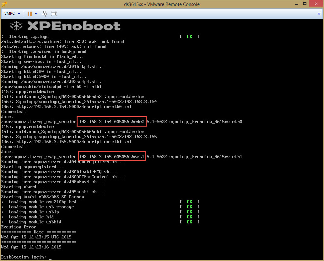
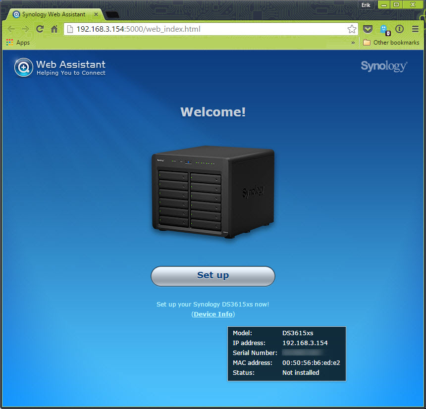
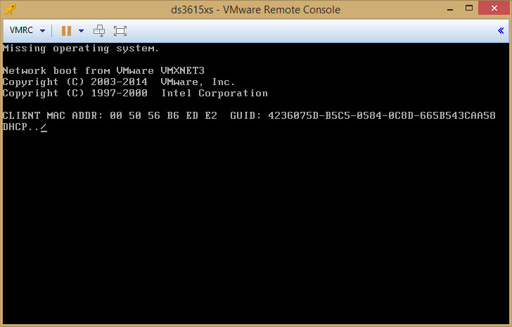
Now you can start the appliance. Look closely at the IP addresses of the appliance and the MAC addresses. You want to start configuring the IP Addresses later on the proper NIC.

12a Start VM and check eth0 eth1

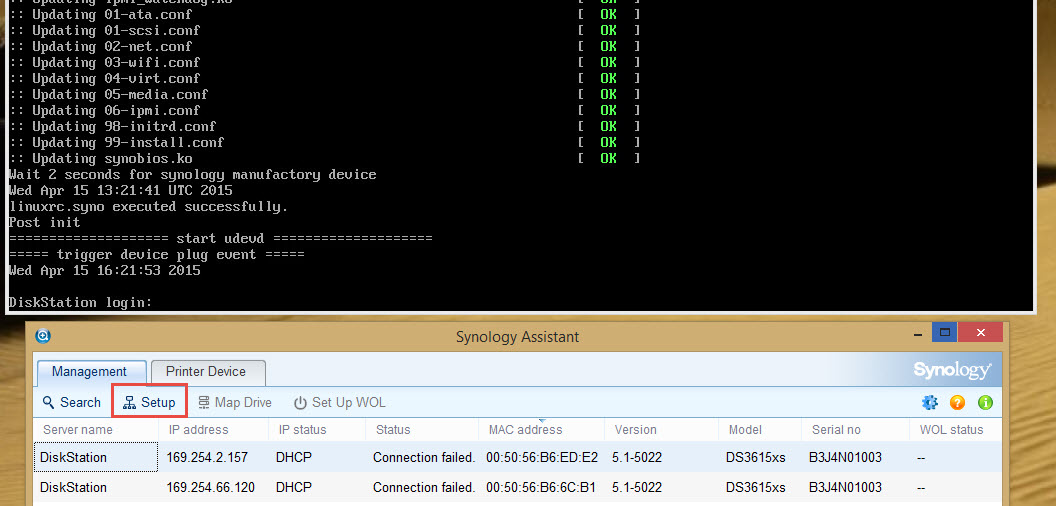
Using the Synology Assistant you can now see your appliance appear on the network.12b - Use Synology Assistant to find new DS3615xs 
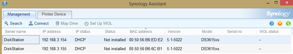
Use your browser and aim it to the IP address shown in the Synology Assistant to do the initial install.

12c - Open the Web Assistant

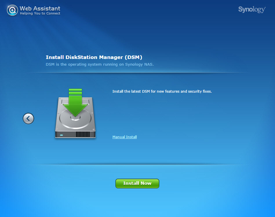
We are installing the DSM using the Manual install.

12d - Install DiskStation Manager

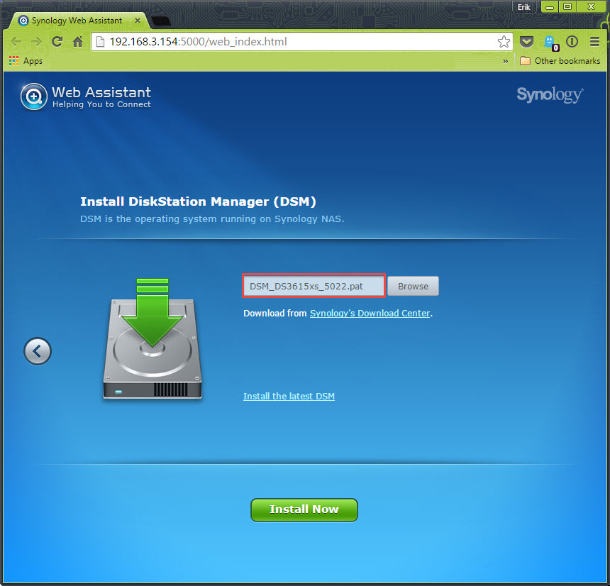
Here you upload the DSM 5.1-5022 pattern file that you retrieved from the Synology download center in the DS3615xs selection.

12e - Select Manual install and select DS3615xs 5022 pat

It will now prompt you that it will erase all partitions on the attached disks of the appliance. This includes the XPEnoboot disk of the appliance.

12f - Format disks with 5022.3 PAT

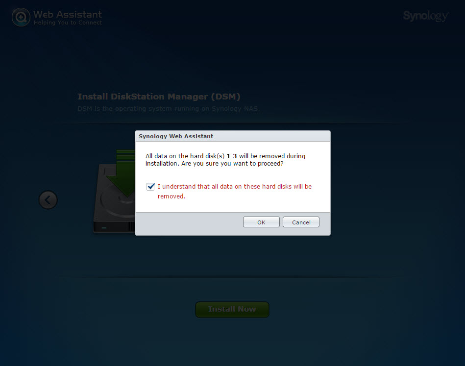
Accordingly the expected behavior now, is that the boot disk is wiped and won’t boot.

13 - Both disk formatted.

Stop the appliance, and using the Datastore browser, you go erase the XPenoboot disk. Upload again for the 2nd time the XPEnoboot_DS3615xs_5.1-5022-3.vmdk in the folder.

14 - Erase XPEnoboot vmdk and replace with original one

3) Configuration using Synology Assistant

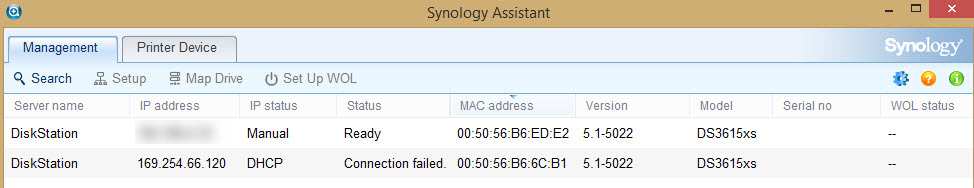
You can now restart the appliance. You will notice that the 2nd time the appliance boots, some of the messages like the IP address are not there anymore. And using the Synology Assistant, you see that the DHCP function isn’t started. The IP addresses are now 169.254.x.y

Select the proper network interface in the Synology Assistant using the MAC address, and select Setup. If you don’t select the proper MAC address you might need to change swap IP addresses later. So save yourself some time, and select the eth0 one.

15 - Reboot DS3615xs and use Synology Assistant
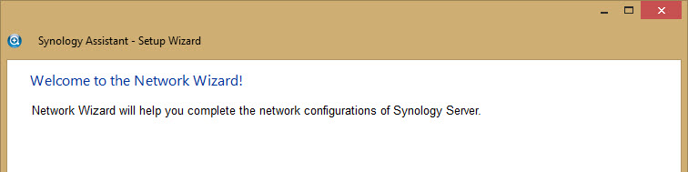
The Synology assistant wizard will now start.

16 - Synology Assistant

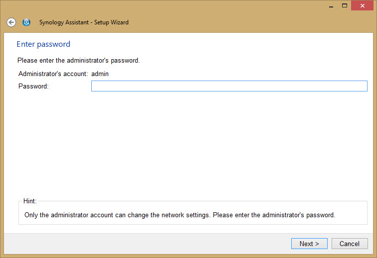
The Admin password at this time is blank, don’t enter any value. You can change the password later.

17 - Synology Assitant - Blank password
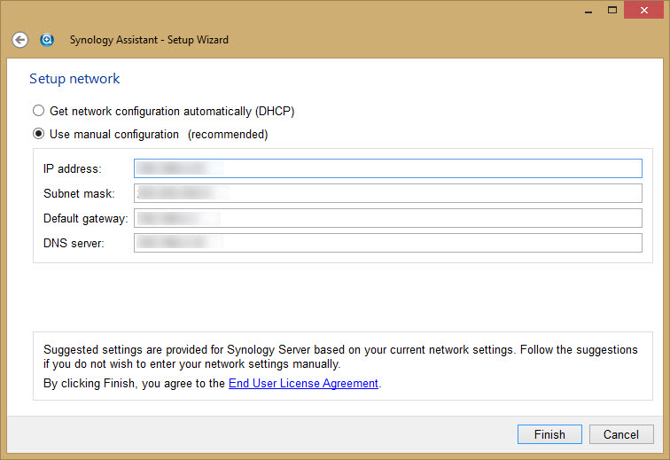
Enter the appliance Network settings.

18 - Synology Assitant - Final Network settings for eth0

Refreshing the Synology Assistant shows that you have the proper IP address now.

19 - Now ready for Web configuration

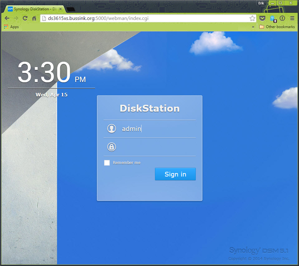
Time to connect to your newly deploy appliance.

20 - Configuration

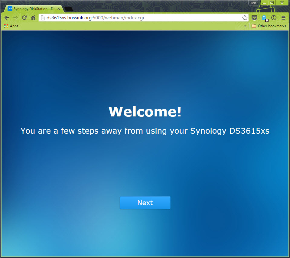
You are now only a few steps away from using your storage appliance.

21 - Web Config

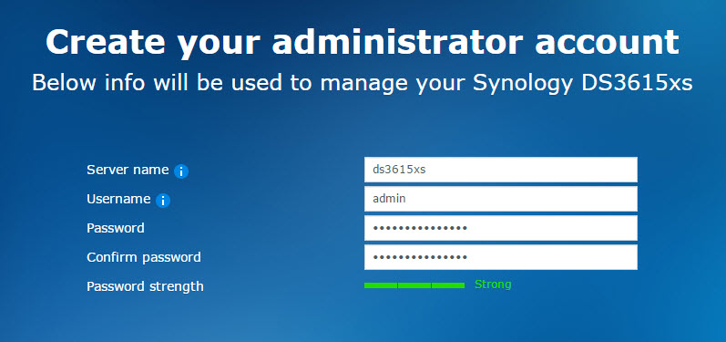
It is now time to change your admin account password.

22 - Server name

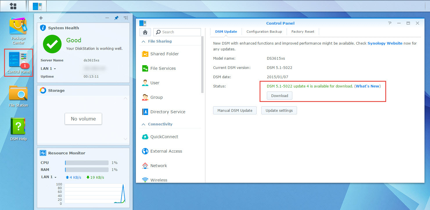
We can now update the DSM 5.1-5022 version to the latest 5.1-5022-5 version. Depending on the CPU of your host, you will never have seen a Synology reboot so fast.

23 Patch DSM

If you intend to use this virtual synology appliance to store data, I recommend you do some conditioning tests first, to see how it reacts in your environment.

I like the flexibility of the virtual synology appliance:

  • Adding a temporary repository for a data migration becomes easy if you have a lot of underlying VSAN datastore space.
  • Want to try out Synology High-Availability, add a 2nd appliance and create the High-Availability cluster.
  • Want to test a Synology with 10GbE interface, easy if your ESXi host has a 10G interface. (*)

In the coming weeks, I’m looking forward to deploy on my VSAN datastore another storage appliances that can scale out in this distributed storage architecture.

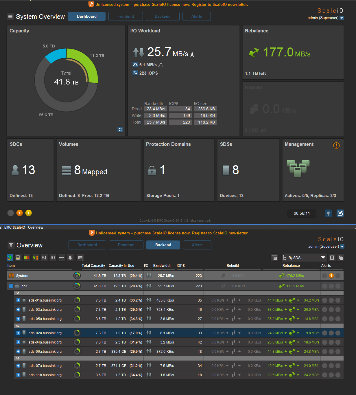
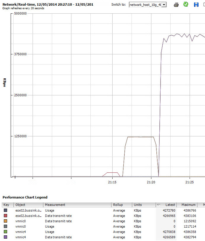
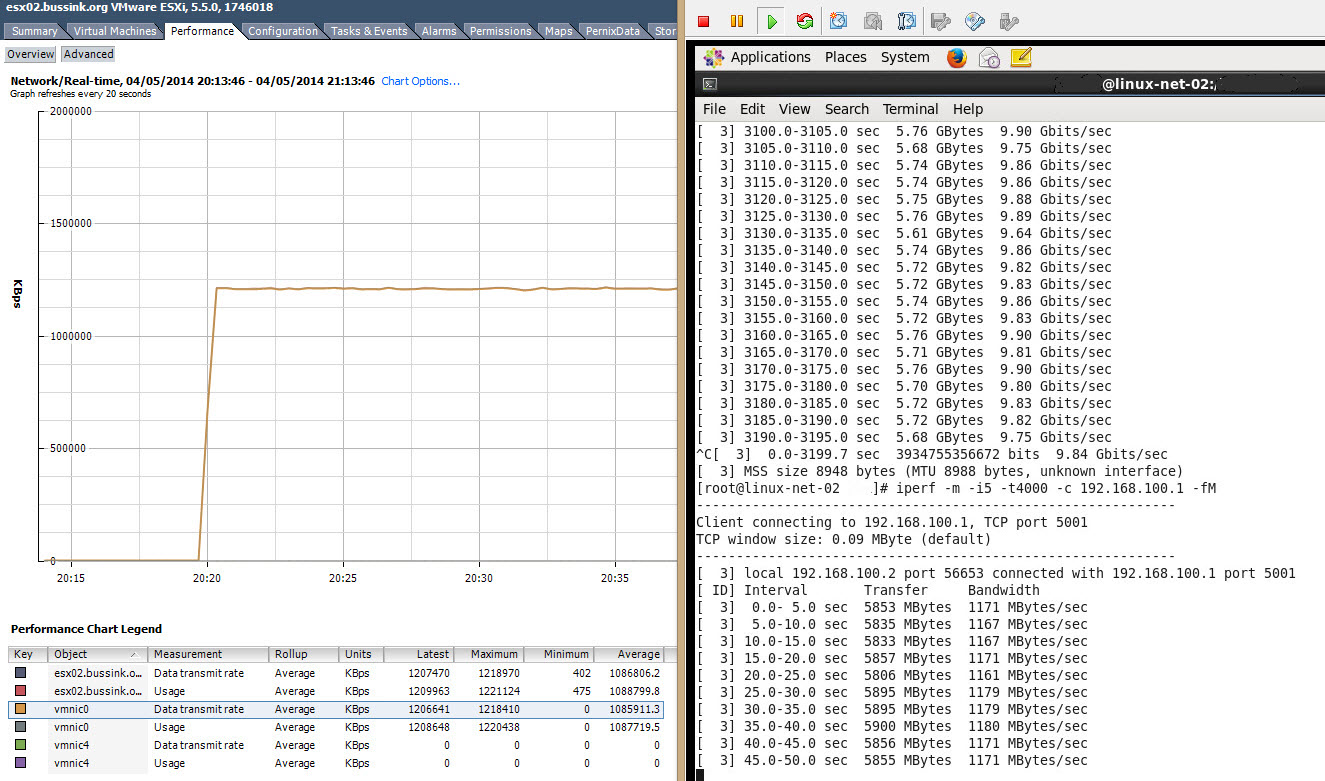
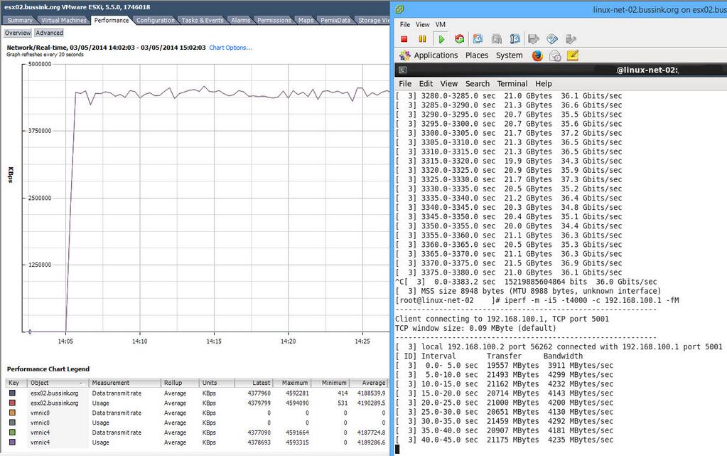
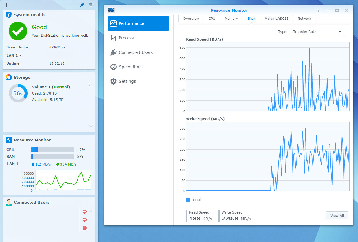
(*) I have found out that while having the virtual synology appliance with 10GbE on the backbone is awesome, yet I ran into upload bandwidth limits trying to upload data. My sources where connected to the core switch over 1GbE links, or the virtual machines being used as a source for testing, has its disk store on 1GbE NFS/iSCSI LUNs. To test the virtual synolgoy I copied large files from various sources.I had three sources pushing out 100-120MB/s, 60-70MB/s and 80-90MB/s of large sequential files to get the 2nd screenshot at the top and see the virtual synology write stats at 220MB/s.

Homelab 2015 Upgrade

Since my last major entry about my Homelab in 2014, I have changed a few things. I added a 2nd cluster based on Apple MacMini (Late 2012), on which I run my OS X workloads, VMware Photon #CloudNativeApps machines, the DevOps Management tools and the vRealize Automation deployed blueprints. This cluster was initially purchased & conceived as a management cluster. The majority of my workload is composed of management, monitoring, analysis and infrastructure loads. It just made sense to swap the Compute and Management cluster around, and use the smaller one for Compute.

Compute_Cluster

Compute Cluster

The original cluster composed of three SuperMicro X9SRH-7TF described in my Homelab 2014 article (more build pictures here) gave me some small issues.

2014

Homelab in December 2014.

I’ve found that the Dual 10GbE X540 chipset on the motherboard does heat up a bit more than expected, and more than once (5x) I lost the integrated Dual 10GbE adapters on one of my hosts, requiring a host power off for ~20 minutes to cool down. In addition, a single 16G DDR3 DIMM was causing one host to freeze once every ~12 days. All the host have run extensive 48 hours memtest86+ checks, but nothing was spotted.  When a frozen VSAN host rejoins the cluster you see the re-synchronization of the data, and at that time, I’m glad to have a 10GbE network switch. In the end, I followed a best practice for VSAN clusters, I extendd the cluster to 4 hosts.

Beginning February I added a single Supermicro X10SRH-CLN4F server with a Intel Xeon E5-2630v3 (8 Cores @2.4Ghz and 64GB of DDR4 memory) to the cluster. This Supermicro X10SRH-CLN4F comes with 4 Intel Gigabit ports, an integrated LSI 3008 SAS 12Gb/s adapter. I also added an Intel X540-T2 dual 10GbE adapter to bring it in line with the first three nodes.

esx01

vSphere 6.0 on Supermicro X10SRH-CLN4F

Having a fourth host means scaling up the VSAN Cluster with an additional SSD and two 4TB SAS drives.

In the past month, the pricing of the Samsung 845DC Pro SSD have drop, to come in the $1/GB range. The Samsung 845DC Pro is rated at 10 DWPD (Disk-Writes-Per-Day) or 7300 TBW (TeraBytes-Written-in-5-years), and its performance is documented at 50’000 Sustained Write IOPS (4K) (Write IOPS Consistency at 95%) [Reference Samsung 845DC Pro PDF, and thessdreview article]. A fair warning for other poeple looking at the Samsung SSD 845DC Pro, it is not on the VMware VSAN Hardware Compatibility List.

Here is a screenshot of the disk group layout of the VSAN Cluster.

vsan_disk_group

VSAN Disk Management

The resulting VSAN configuration is now 28TB usable space.

vsan

Here is a screenshot of the current Management Cluster.

Management Cluster

This cluster having grown, is now also generating additional heat. It’s been relocated in a colder room, and I had a Three Phase 240V 16A electricity line put in.

Management Cluster (April 2015)

Management Cluster (April 2015)

My external storage is still composed of two Synology arrays. An old DS1010+ and a more recent DS1813+ with a DX513 extension. At this point, 70% of my virtual machine datasets are located on the VSAN datastore.

Synology DS1813+ Storage Manager

Reviewing this article, I realize this cannot quantify as a homelab anymore… its a home datacenter… guess I need a new #HomeDC hashtag…

Notes & Photos of the Homelab 2014 build

I’ve had a few questions about my Homelab 2014 upgrade hardware and settings. So here is a follow-up. This is just a photo collection of the various stages of the build.  Compared to my previous homelabs that where designed for a small footprint, this one isn’t, this homelab version has been build to be a quiet environment.

I started my build with only two hosts. For the cases I used the very nice Fractal Design Define R4. These are ATX chassis in a sleek black color, can house 8x 3.5″ disks, and support a lot of extra fans. Some of those you can see on the right site, those are Noctua NF-A14 FLX. For the power supply I picked up some Enermax Revolution Xt PSU.

IMG_4584

For the CPU I went with the Intel Xeon E5-1650v2 (6 Cores @3.5GHZ) and a large Noctua NH-U12DX i4. The special thing about the NH-U12DX i4 model is that it comes with socket brackets for the Narrow-Brack ILM that you find on the Supermicro X9SRH-7TF motherboard.

IMG_4591

The two Supermicro X9SRH-7TF motherboards and two add-on Intel I350-T2 dual 1Gbps network cards.

IMG_4594

Getting everything read for the build stage.

On the next photo you will see quiet a large assortment of pieces. There are 5 small yet long lasting Intel SSD S3700 100GB, 8x Seagate Constellation 3TB disks, some LSI HBA Adapters like the LSI 9207-8i and LSI 9300-8i, two Mellanox ConnectX-3 VPI Dual 40/56Gbps InfiniBand and Ethernet adapters that I got for a steal (~$320USD) on ebay last summer.

IMG_4595

You need to remember, that if you only have two hosts, with 10Gbps Ethernet or 40Gbps Ethernet, you can build a point-to-point config, without having to purchase a network switch. These ConnectX-3 VPI adapters are recognized as 40Gbps Ethernet NIC by vSphere 5.5.

Lets have a closer look at the Fractal Design Define R4 chassis.

Fractal Design Define R4 Front

Fractal Design Define R4 Front

The Fractal Design Define R4 has two 14cm Fans, one in the front, and one in the back. I’m replacing the back one with the Noctua NF-A14 FLX, and I put one in the top of the chassis to extra the little warm air out the top.

The inside of the chassis has a nice feel, easy access to the various elements, space for 8x 3.5″ disk in the front, and you can push power-cables on the other side of the chassis.

Fractal Design Define R4 Inside

Fractal Design Define R4 Inside

A few years ago, I bought a very nice yet expensive Tyan dual processor motherboard and I installed it with all the elements before looking to put the CPU on the motherboard. It had bent pins under the CPU cover. This is something that motherboard manufacturers and distributors have no warranty. That was an expensive lesson, and that was the end of my Tyan allegiance. Since then I moved to Supermicro.

LGA2011 socket close-up. Always check the PINs. for damage

LGA2011 socket close-up. Always check the PINs. for damage

Here is the close up of the Supermicro X9SRH-7TF

Supermicro X9SRH-7TF

Supermicro X9SRH-7TF

I now always put the CPU on the motherboard, before the motherboard goes in the chassis. Note on the next picture the Narrow ILM socket for the cooling.

Intel Xeon E5-1650v2 and Narrow ILM

Intel Xeon E5-1650v2 and Narrow ILM

Here is the difference between the Fractal Design Silent Series R2 fan and the Noctua NF-A14 FLX.

Fractal Design Silent Series R2 & Noctua NF-A14 FLX

Fractal Design Silent Series R2 & Noctua NF-A14 FLX

What I like in the Noctua NF-A14 FLX are the rubber hold-fasts that replace the screws holding the fan. That is one more option where items in a chassis don’t vibrate and make noise. Also the Noctua NF-A14 FLX runs by default at 1200RPM, but you have two electric Low-Noise Adapters (LNA) that can bring the default speed down to 1000RPM and 800RPM. Less rotations equals less noise.

Noctua NF-A14 FLX Details

Noctua NF-A14 FLX Details

Putting the motherboard in the Chassis.

IMG_4623

Now we need to modify the holding brackets for the CPU Cooler. The Noctua NH-U12DX i4 comes with Narrow ILM that can replace the ones on it. In the picture below, the top one is the Narrow ILM holder, while the bottom one still needs to be replaced.

IMG_4621

And a close up of everything installed in the Chassis.

IMG_4629

To hold the SSD in the chassis, I’m using an Icy Dock MB996SP-6SB to hold multiple SSD in a single 5.25″ frontal slot. As SSD don’t heat up like 2.5″ HDD, you can select to cut the electricity to the FAN.

IMG_4611

This Icy Dock MB996SP-6SB gives a nice front look to the chassis.

IMG_4631

How does it look inside… okay, honest I have tied up the sata cables since my building process.

IMG_4632


Here is the picture of my 2nd vSphere host during building. See the cabling is done better here.

IMG_4647


The two Mellanox ConnectX-3 VPI 40/56Gbps cards I have where half-height adapters. So I just to adapt a little bit the holders so that the 40Gbps NIC where firmly secured in the chassis.

IMG_4658

Here is the Homelab 2014 after the first build.

IMG_4648


At the end of August 2014, I got a new Core network switch to expand the Homelab. The Cisco SG500XG-8F8T, which is a 16x Port 10Gb Ethernet. Eight ports are in RJ45 format, and eight are in SFP+ format, and one for Management.

Cisco SG500XG-8G8T

Cisco SG500XG-8G8T

I build a third vSphere host using the same config as the first ones. And here is the current 2014 Homelab.

Homelab 2014

Homelab 2014

And if you want to see what the noise is at home, check this Youtube movie out. I used the dBUltraPro app on the iPad to measure the noise level.

And this page would not be complete if it didn’t have a vCenter cluster screenshot.

Homelab 2014 Cluster

Upgrading LSI HBA 9300-8i via UEFI (Phase 06)

Here is a resume on how to upgrade a LSI SAS3 HBA 9300-8i card to the latest BIOS & Firmware using the UEFI mode. This is applicable to my homelab Supermicro X9SRH-7TF or any other motherboard with UEFI Build-In EFI Shell. I’ve found that using the UEFI mode to be more practical than the old method of a MSDOS bootable USB key. And this is the way more and more Firmware and BIOS will be released.

Tom and Duncan showed  how to upgrade an LSI 9207-4i4e from within VMware vSphere 5.5 CLI. In this article I’m going to show you how to use the UEFI Shell for the upgrade.

Preparation.

First you need to head over to the LSI website for your HBA and download a few files to your computer. For the LSI HBA 9300-8i you can jump to the Software Downloads section. You want to download three files, extract them and put the files on a USB key.

The Installer_P4_for_UEFI which contains the firmware updater sas3flash.efi that works with P06. You can retrieve it using this dropbox link as it’s disappeared from the LSI download site.

The SAS3_UEFI_BSD_P6 which contains the BIOS for the updater (X64SAS3.ROM)

The 9300_8i_Package_P6_IR_IT_firmware_BIOS_for_MSDOS_Windows which contains the SAS9300_8i_IT.bin firmware and the MPTSAS3.ROM bios.


lsi9300_8i_download

At this point you put all those extract files mentioned above on a USB key.

lsi9300_p06_usbdos


You reboot your server, and modify the Boot parameters in the BIOS of the server to boot in UEFI Built-In EFI Shell.

UEFI_Build-In_EFI_Shell

Upgrading BIOS & Firmware.

When you reboot you will be dumped in the UEFI shell. You can easely move to the USB key with your programs using

UEFI_booting

And lets move over to the USB key. For me the USB key is mapped as fs1: but you could also have a fs0:

A quick dir command will list the files on the USB key.

uefi_dir

Using the sas3flash.efi -list command (extracted from the Installer_P4_for_UEFI file) we can list the local LSI MPT3SAS HBA adapter, see the SAS address and see the various versions of the Firmware & BIOS and UEFI BSD Bios.

sas3flash_list

There are three components that we want to patch, the Firmware, the BIOS and the UEFI BSD Code.

Here we start by upgrading the UEFI BSD BIOS. Using the sas3flash.efi we can fine tune with the SAS address of the controller, and select the X64SAS3.ROM file found in the SAS3_UEFI_BSD_P6 download. As you see, the –c Controller command allows you to specify to which adapter the BIOS is loaded. You can enter the number 0 or the SAS Address. sas3flash.efi -c 006F94D30 -b X64SAS3.ROM

sas3flash_bios

The next step is upgrade the Firmware with the SAS9300_8i_IT.bin found in the 9300_8i_Package_P6_IR_IT_firmware_BIOS_for_MSDOS_Windows file. sas3flash.efi -c 006F94D30 -f SAS9300_8i_IT.bin

sas3flash_firmware

The last part is to upgrade the MPTSAS3.ROM file which contains the BIOS of the LSI adapter. Here again we use sas3flash.efi -c 006F94D30 -b MPTSAS3.ROM.


The end result once Phase 06 firmware and bioses have been install is the following sas3flash.efi -list

lsi9300_8i_phase06


  • Firmware Version 06.00.00.00
  • BIOS Version 08.13.00.00
  • UEFI BSD Version 07.00.00.00

Now reboot the server, and make sure to change back your Boot option in the server BIOS to your USB key or harddrive that contains the vSphere hypervisor.


Speed testing 40G Ethernet in the Homelab

In my previous post, I described the building of two Linux virtual machines to benchmark the network. Here are the results.

homelab_network_1g_10g_40g_iperf_testing


The first blip, is running iperf to the maximum speed between the two Linux VMs at 1Gbps, on separate hosts using Intel I350-T2 adapters.

The second spike (or vmnic0), is running iperf to the maximum speed between two Linux VMs at 10Gbps. The two ESXi hosts are using Intel X540-T2 adapters.

The third mountain (or vmnic4) and most impressive result is running iperf between the Linux VMs using 40Gb Ethernet. The two ESXi hosts are using Mellanox ConnectX-3 VPI adapters.

The Homelab 2014 ESXi hosts, uses a Supermicro X9SRH-7TF come with an embedded Intel X540-T2. We can more closely see the  results of the iperf test at 10Gbps in the following picture.

homelab_network_10g_iperf_testing

I also got last summer from Ebay, a set of Mellanox ConnectX-3 VPI Dual Adapters for $300. These cards support InfiniBand 40Gb/s and 56Gb/s, and Ethernet at 10Gb/s and 40Gb/s. By default, vSphere 5.5 recognizes these adapters as 40Gb Ethernet adapters. And I really wanted to test these adapters at 40Gb Ethernet… and the results are great. I can push upto 37.3 Gbits/sec thru a single 40Gb Ethernet link, or 4299 MBytes/sec. Just have a peak at the following screenshot.

homelab_network_40g_iperf_testing

I guess having 40Gb Ethernet for vMotion is too fast…  The vMotion of a 12GB VM takes 15-16 seconds, of which only 3 seconds are used for the memory transfer, the rest is the memory snapshot, processes freeze, cpu register cloning and the rest.

All the test run at 10Gb Ethernet and 40Gb Ethernet where done with Jumbo Frames. For 40Gb Ethernet it makes real (x 2.5) difference in bandwidth.

This was a fun piece to lab in the homelab.